Designing a Complex Software Stack with Hardware Safety Assurance
Integration of the Arm Software Test Library with the Wind River Safety-Certifiable Hypervisor
EXECUTIVE SUMMARY
Functional safety is increasingly critical across a range of markets, and more powerful and complex software solutions are required in areas such as autonomous driving and related services, intelligent avionics devices, and self-organized factory floors. The higher the criticality and the less human control is involved, the higher the inherent risk for the airplane or car, as reflected by the Safety Integrity Level or Design Assurance Level associated with the device.
Meeting the requirements of safety standards such as ISO 26262 (automotive) and IEC 61508 (industrial) for high integrity levels requires rigid formal methodologies and documentation, not only in the development process of hardware and software but also the continuous monitoring and reporting of random hardware faults during the operation of the device. One of the methodologies commonly used for highest safety integrity is Dual-Core Lockstep, whose output from redundant CPUs is continuously compared to ensure detection of any fault that leads to output corruption. This type of system is expensive, in the need to double the CPU area, and it becomes less viable when applications require the computational power of modern multi-core SoCs with four or even 16 processor cores. In this case, the use of self-testing techniques such as Software Test Libraries (STL) is a common approach to achieve the integrity requirements of the standards.¹
Managing the complexity of a modern multi-core processor or system-on-chip (SoC) requires a powerful operating system (OS) platform that offers the application developer an abstract yet flexible programming environment such as AUTOSAR Adaptive, as well as robust techniques for separation, partitioning, and fault containment, as the foundation to achieve formal safety certification.
The integration of a software test library, with assumptions of use guided by the internals of the processor design and a complex software stack for a multi-core partitioned OS, touches different facets of the design of safety-critical software systems. While performance and the amount of processor time required for the test library might be known off the top of one’s head, design choices about where the STL is integrated in the software stack can have a significant influence on system integration and validation aspects.
OVERVIEW
The Wind River® Helix™ Virtualization Platform (Helix Platform) is a true Type 1 hypervisor–based operating platform enabling mixed criticality OS and applications to run on multi-core processors. That requires robust separation and design to achieve certification to the highest levels of safety criticality, such as ISO 26262 ASIL D, DO-178C Level A, or IEC 61508 SIL 3 and SIL 4. Leveraging years of experience and industry leadership in safety-critical and embedded hypervisor software technologies, Helix Platform is building on the highly successful VxWorks® 653 Multi-core Edition, which is used in multi-core avionics systems up to the highest safety assurance level.
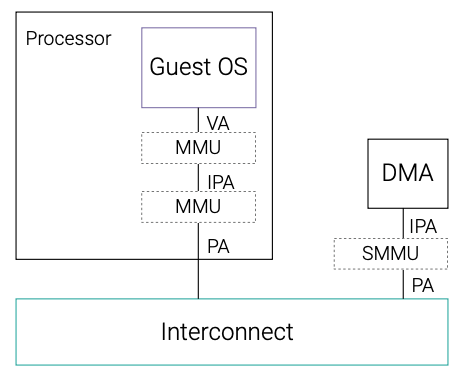
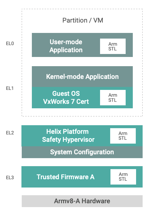
Helix Platform architecture leverages advanced processor protection features of the Arm® v8 architecture such as hypervisor and supervisor privilege levels, and the memory management unit (MMU) and system memory management unit (SMMU) to provide separation and fault containment for applications in independent partitions, as seen in the figure.
Designing a safety-certified system with Helix Platform requires formal documentation of processes, requirements, design, and verification for the complete codebase of the OS software. Wind River addresses this need with a commercial off-the-shelf evidence documentation package, including a safety manual and an automated verification test harness to verify the operation of the software on a specific customized hardware, such as an ADAS controller board or the primary flight display computer of an aircraft.
However, the safety processes and documentation for software only address systematic errors under the assumption that the underlying processor hardware is working correctly. At the same time, the safety standards authors are aware of the additional risk of statistical electrical or mechanical failure of hardware. Similarly strict certification activities are therefore required on the hardware side, including continuous monitoring to prove the required failure rates, such as <1 failure per 1 billion hours of operation at IEC 61508 SIL 4 or ISO 26262 ASIL D for systems or subsystems.
To help OEMs achieve higher hardware diagnostic coverage more efficiently, Arm produces software test libraries (STL) for many of its processors. Compared to other diagnostic techniques such as logic built-in self-tests (LBIST), STLs are more flexible and can save significant power and silicon area. Along with source code, STL users get access to a safety package including a safety manual and FMEDA report to assist in integrating the STL within their safety concept.
The integration of this low-level STL with a complex multi-tiered OS creates challenges that are further amplified by the restrictions of safety-critical software architecture design. The frequency and execution time of the STL to achieve diagnostic coverage has direct impact on the available computational power for OS and applications, and this impact needs to be quantified.
This paper will discuss different approaches for the integration of STL and OS and provide results based on a demonstrator using a Xilinx Zynq® UltraScale+ MPSoC with four Arm Cortex-A53 cores.
ARCHITECTURE
Hardware Architecture
The Zynq® UltraScale+™ MPSoCs from AMD Xilinx form a scalable portfolio of heterogenous multi-processing devices. This hardware platform is based on the combination of 16nm FinFET+ programmable logic with processing systems built on Cortex-A53 and Cortex-R5(F) CPUs and the Arm Mali-400 MP2 GPU.
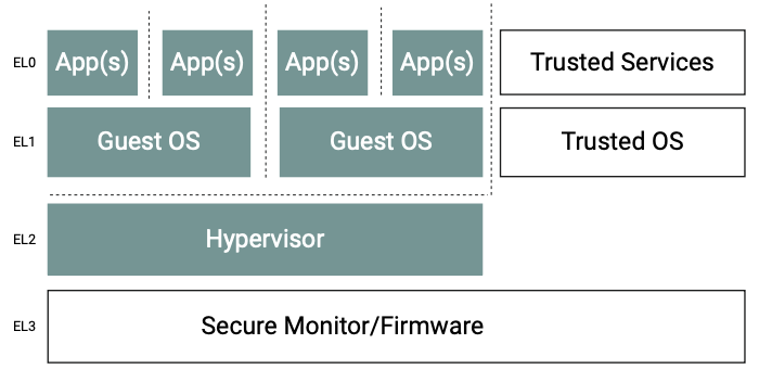
Central to the application processing unit, Cortex-A53 is a 64-bit capable processor IP, released in 2014 and based on Armv8.0-A architecture. It features hardware virtualization capabilities to enable simultaneous execution and separation of multiple guest OSes under the control of a hypervisor, such as Helix Platform. To realize this, the Cortex-A53 processor implements Exception levels EL 0 to EL 3, each with increasing execution privileges. A typical software stack could be mapped to different Exception levels as per the figure above.
Helix Platform Architecture
Helix Platform uses a Type 1 hypervisor — also known as a bare metal hypervisor — that runs directly on the processor to provide near-native real-time performance, including the direct delivery of interrupts to the guest OS. This approach enables higher performance, determinism, scalability, and small footprint with minimal overhead suitable for safety certification. It contrasts with the Type 2 hypervisor, which is an application running in a general purpose or real-time OS with a focus on convenience, abstraction, or emulation. It can even provide the option of over-provisioning existing hardware resources, usually for IT use cases.
The Helix Platform Type 1 hypervisor uses the processor’s dedicated hypervisor privilege level and hardware virtualization support, enabling various 32-bit and 64-bit guest OSes and associated applications to run at separate Exception levels of the Arm architecture inside virtualized machines (VM), including support for OS-less bare metal virtual machines. The hypervisor uses MMU and SMMU capabilities to ensure isolation and fault containment for the different VMs to maximize safety and security, and to enable consolidation of multiple independent safe and non-safe applications into a single processing platform. In the context of avionics systems, the combination of an isolated guest OS and application is referred to as a partition.²
For the Armv8-A architecture, Helix Platform builds the hypervisor and the VxWorks guest OS from source code using modern compiler toolchains based on Clang/LLVM, which provide support for the latest C and C++ features and standards and performance benefits, such as fast compilation times, low memory usage, superior code optimization, and integration with third-party tools for code analysis and quality assurance.
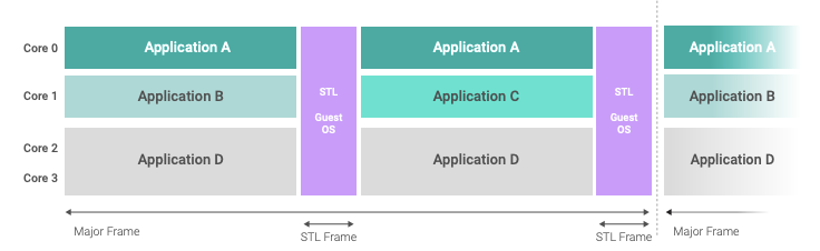
The hypervisor scheduler for the VMs uses a frame scheduler scheme based on a repetitive sequence of fixed time windows, called a major frame, as depicted below. Every VM in the major frame has a time budget configured at build time and validated with the platform. This provides the option of sharing a processor core between multiple VMs. Helix Platform can schedule one VM in parallel on multiple cores within the same time window, thus enabling multi-core VMs, often referred to as SMP guest OSes. The hypervisor can synchronize the major frames on processor cores, or cores or groups of cores can run on independent schedules.
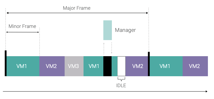
Once the initialization phase is completed, the hypervisor is, for the most part, responsible only for switching the VMs according to the schedule, arbitration and emulation of hardware resources shared between VMs, and system-level error handling. Dedicated hypervisor services such as major frame schedule changes can be requested from a trusted guest OS using a hypercall API implemented with the hypervisor call (HVC) instruction of Armv8-A architecture. The implementation of hypervisor services is handled mainly within separate single-core threads defined in a static table — the so-called managers. Within each time window, both managers and VMs are scheduled in a priority-based scheme, so that high-priority managers such as the system-level exception handling can preempt the execution of a VM within its time window. Managers can also be restricted to be scheduled only in specific time windows instead of a VM, a technique often used to allot dedicated time for system-wide functionality that could otherwise interfere with VM execution, such as flushing I/O queues to storage or network hardware.
The hypervisor is leveraging the dedicated Exception level (EL) 2 of the Armv8 architecture, whereas the guest OS is executing on EL 1, with the added option of further separation of applications using EL 0. The Trusted Firmware-A (TF-A) at the highest EL 3 of the processor is outside the scope of the OS platform, and secure monitor calls (SMC) are usually not performed during normal operation.
The safety evidence material from Wind River covers the VxWorks Cert Edition guest OS to implement safety-critical applications on EL 1, with optional use of EL 0 for further separation within the partition.
Fault containment and isolation between VMs is implemented on the hypervisor level, and an ARINC 653–compliant hierarchical health monitoring framework provides failure reporting, escalation, and handling according to a table-based configuration. This approach enables the system integrator to specify the course of action to take in the event of specific errors as part of the overall system configuration. Examples for such actions are the warm restart of a VM following a floating-point exception in the application or switching to a safe/degraded operation mode schedule upon ECC memory errors.
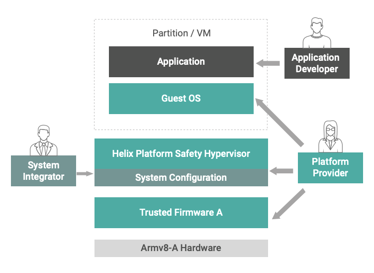
Helix Platform is designed to support customers in the clear separation of roles and responsibilities in their system lifecycle by enabling independent development along with incremental updates of the platform and application code as well as the system configuration through a technique called independent build, link, and load (IBLL). This is based on the roles of Platform Provider, Application Developer, and System Integrator as defined in the DO-297 Standard3 for avionics systems and shown in the figure on the previous page. However, these concepts and workflows are applicable and beneficial for any project and industry, and Helix Platform enables various degrees of responsibility separation for the specific project context. The roles, responsibilities, and system lifecycle considerations can be decisive factors for software architecture aspects, as the integration of the STL will show.
Arm Software Test Library (Software BIST)
Arm STLs are libraries containing software functions that check the presence of permanent faults within the processor logic. Each STL is developed and optimized for a specific Arm processor, which enables targeting of explicit nodes in the design. STLs provide an additional diagnostic mechanism, which can be used to assist in achieving the overall system safety metric requirements.
STLs are commonly employed in applications with lower safety integrity levels such as SIL 2 or ASIL B, where duplication of logic such as DualCore Lockstep can be avoided to preserve silicon area and reduce cost and power requirements. Although less common, high safety integrity applications (e.g., ASIL D, SIL 3) can also benefit from STLs at boot time to potentially stimulate hardware faults not exercised by application code. The following figure provides a qualitative comparison of STLs versus other safety mechanisms.
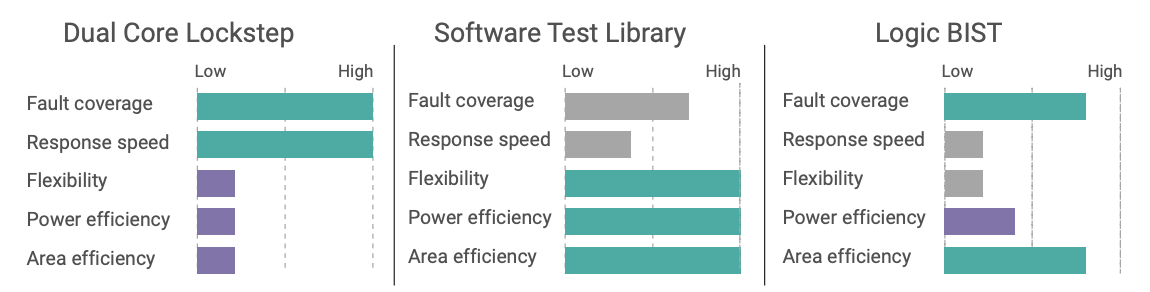
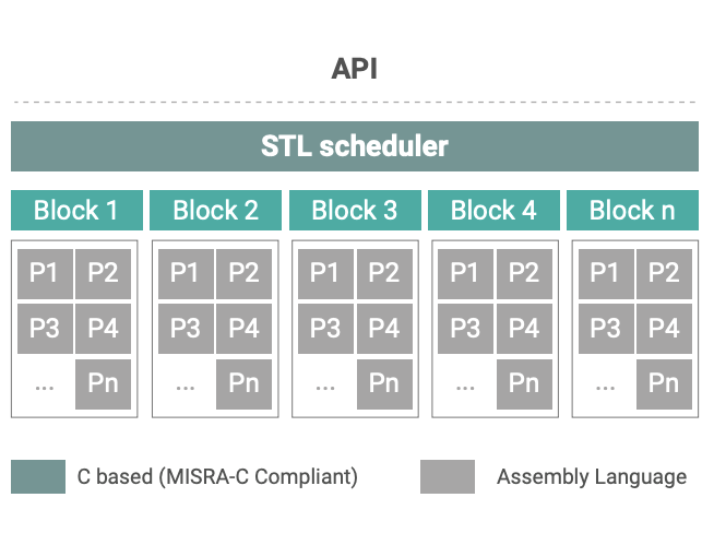
Functional tests in Arm STLs are coded in Assembly to deliver deterministic execution and fault coverage, while requiring minimal code footprint. These functions are typically invoked from the STL’s C-based scheduler in roundrobin fashion. The Cortex-A53 STL used in this example, for instance, requires about 100KB ROM and 10KB RAM. It fully executes in only 161K CPU clock cycles in EL 3 with an interrupt-disabled window of just 6,200 cycles, or about 5µs. STL basic software architecture is shown in the figure at right.
Most of the Cortex-A53 STL functions can be executed in the OS at EL 1 or the hypervisor at EL 2. However, to achieve maximum coverage of random permanent faults in the CPU, control register testing must execute with the highest privilege in EL 3. Fully executing all Cortex-A53 STL tests provides single-point fault metric (SPFM) coverage for processors, including memories based on netlist ports. This means that when building on additional hardware safety mechanisms such as error correction code (ECC), it becomes much easier to exceed the recommended 90% SPFM for ISO 26262 ASIL B.
INTEGRATION OF THE ARM STL AND HELIX PLATFORM
The build process of the STL outputs a set of object files for the Armv8 architecture that must be linked to the operating software so that the tests can run on the respective Exception level within the intervals derived from the FMEDA of the hardware. Entry points into the STL are functions to set up and run the test suite, with guidance and example code provided along with the User’s Guide.
When running all STL tests across EL 1, EL 2, and EL 3 to achieve maximum coverage, it usually requires linking the library objects separately to each layer of the software stack. This results in multiple copies of the same objects at runtime, as the figure at right shows. However, this overhead is usually acceptable if the size of the STL object file is less than 150KB. In addition, the object files can be reduced to only the subset of tests for the respective Exception level. This instantiation only creates a challenge for the TF-A layer in the demonstrator, where adding the STL exceeds the platform-specific limitations for on-chip memory that stores the firmware by default. Selecting the option to build the TF-A for RAM storage solves this problem. In an actual safety system, and depending on the safety requirements, users can also opt to run a subset of the library functions executed at lower Exception levels, e.g., EL 0 and EL 1, to benefit from inherent containment.
In a standard system setup, the TF-A is loaded before the boot loader and the OS are loaded. The secure monitor part of the TF-A that runs at EL 3 cannot be replaced or extended by any other part in the software stack during runtime, and therefore execution of the STL tests at EL 3 demands linkage of the STL with the TF-A. Execution of the EL 3 tests is initiated from the hypervisor level using the SMC instruction4 with a custom handler in the TF-A.
Starting the STL tests in the guest OS for the EL 1 and in the hypervisor for EL 2 on a specific processor core is a trivial call to the Arm functions, and execution in the hypervisor and the TF-A can be triggered from the lower Exception levels using hypercall and secure monitor call API. The use of these functions must be assessed within the overall system architecture, in particular for safety-certifiable systems that have strict requirements for timing and determinism.
The main consideration for starting execution of the STL should be the alignment with the overall system timing and scheduling and how the guest OS will utilize different processor cores within the schedule. This assessment must include both the frequency and duration of the STL execution for each Exception level, and the potential impact on the guest OS or application execution as well as jitter caused by interrupt locking during the tests.
Additional requirements can be introduced by SoC designs with heterogenous processor cores or clustering of cores, as well as other hardware test libraries alongside the Arm STL to monitor SoC vendor IP or other peripherals or FPGA functions. Such considerations are outside the scope of this paper, but the example in this paper can provide guidance.
Three different options for integration of the Arm STL with Helix Platform can be considered:
– Option 1: Dedicated partition for test execution
– Option 2: Test execution started from a regular guest OS within the time allotted to the partition
– Option 3: Test execution within the hypervisor
The following sections give an overview on the implementation details and considerations around each of these options. Common to all three options is the reporting of error conditions when the STL fails, which can use the existing health monitoring framework of Helix Platform. This framework enables data-driven configuration by the system integrator according to the error policy of the system, with customizable error handlers to reboot the system, switch to safe or degraded operation modes, or simply to record found issues and await several failure occurrences before triggering further actions.
Option 1: Dedicated Test Partition
The dedicated partition for executing the Arm STL has advantages from a system design perspective, as it gives the system integrator full control over the scheduling of the tests, as part of the overall system schedule or on a per-processor core base, and fault detection is separated from the application level.
The footprint of a dedicated test partition is primarily dependent on the guest OS, where a safety-certifiable VxWorks guest OS usually requires not more than 5 MB of storage and 64 MB of runtime memory. When execution time and footprint are even more critical, the support for bare-metal OS-less VMs in Helix Platform can be leveraged to replace the guest OS with a basic loop to execute the Arm STL and report errors to the health monitoring framework using the low-level hypercall API of the hypervisor.
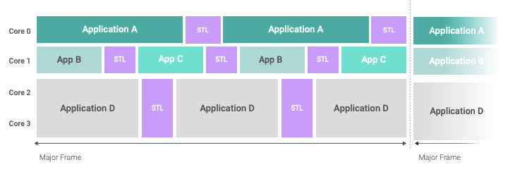
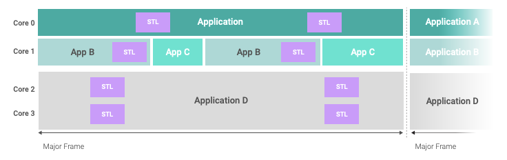
The following figures show two potential system schedules with multiple application payloads and the test partition scheduled intermittently. In the first figure, a single test partition with its own multicore guest OS will execute on all four cores of the system at the same time, and scheduling the execution of the STL on each core is implemented within the guest OS.
Defining separate test partitions for each core is a way to independently schedule STL execution on each core, as depicted in the next figure. This can bring significant advantages in system configurations where the cores host different applications with different safety-criticality levels and requirements on scheduling or periodicity. The Arm STL does not require to stop parallel application processing on other processor cores. This approach consumes more runtime memory, as the test partition will be instantiated four times in memory and might require more analysis on interference and contention due to parallel scheduling of application payloads and STL on different cores.
The integration example will be based on the system schedule in the first figure, with one test partition instance executing on all cores in parallel.
Tests on the Exception levels 2 (hypervisor) and 3 (TF-A) are executed synchronously on the core where the test partition triggered the execution with the respective hypercall API. There is no impact to the other cores, where execution continues in the context and Exception level of the currently scheduled guest OS. System scheduling is also not impacted by the switch to EL 2 or EL 3 unless interrupts are masked by the STL at the higher privilege levels, while a VM switch is due based on the schedule. The system integrator is responsible for assessing this as part of the worst-case execution time scenarios for the STL and must ensure a sufficient time budget for test execution.
Option 2: Test Execution Within the Hypervisor
Since the Arm STL only requires execution of tests on EL 2 and EL 3 for highest coverage, the test partition could be more efficient if it only runs at EL 2 (hypervisor) level without the need for an extra virtual machine at EL 1. This is possible in the Helix hypervisor when the STL execution is implemented with a manager thread inside the hypervisor, and the test partition time window is configured to schedule the manager instead of a VM. The implementation of the manager requires more care to make sure the manager does not interfere with the normal operation of the hypervisor or the time partitioning. Since managers are single-core threads, the STL execution can be scheduled in parallel or independently on each core, as with the test partitions.
While the demonstrator will show that the performance gain by removing the switch to a different VM is only modest, the managerbased implementation has more significant impact on the memory footprint, as there is no need for one or more additional safetycritical guest OS instances to start the STL. The disadvantage is that managers do not have access to advanced services provided by the guest OS, such as file systems or networking to propagate or store test results.
Hooks in the hypervisor offer the ability to add custom functions that get called upon in internal events of the hypervisor, allowing implementing the call to the STL as part of the VM switch event. Using this approach, the STL execution could be completely hidden inside the hypervisor and altogether removed from the time window configuration.
However, loading STL execution overhead onto the schedule switch event or consuming time from the defined VM time windows will increase delay and jitter of the system and contradict the hypervisor’s design, aiming to keep the overhead of VM switching at the minimum by leveraging the advanced processor virtualization features in the Armv8 architecture. Due to these limitations, the STL execution on hypervisor events should only be considered for special use cases and is not implemented in this paper.
Option 3: Test Execution Within Application Context
When the overall system architecture makes the use of a dedicated test partition difficult, or when the STL integration should be the responsibility of the application developer, the test execution can also be started from a thread inside a regular application partition. The VxWorks guest OS provides different concepts to define timely execution of the STL within the required periods of time, such as periodic processes with configurable deadlines to monitor jitter, or a time-partitioned scheduler on the guest OS level to define time windows for threads as well.
Execution of the STL on EL 2 and EL 3 will be under the same conditions as for the dedicated test partition, but execution time for the STL will be deducted from the time budget of the application processes inside the partition thread. Moreover, the application partition must be granted permission to make hypervisor calls, which must be balanced with security and safety requirements.
The decision to synchronize the STL execution within different applications on different cores would be the responsibility of application developers in this scenario. This can become impossible if applications are supplied by different third parties potentially unbeknownst to each other. Since the Arm STL can be executed independently on each processor core, such synchronization may not be necessary and should be confirmed by the system integrator.
Timely execution of the STL within the required intervals for the system FTTI (Fault Tolerant Time Interval) must be ensured on the application level by using appropriate thread priorities and could be augmented by an additional level of system-wide monitoring on the hypervisor level, which can preempt any application processes.
Interrupt locking during the STL execution needs special consideration in this scenario, where, for example, a periodic guest OS system clock tick must not overlap with the test library, as the interrupt locking sections could cause a tick miss with impact on periodic process timing. The dedicated test partition, with its separate VM context, leverages the ability of the hypervisor to manage the consistent time base for the application guest OS.
A big advantage of this architecture is the required processor time. Switching tasks is only slightly less costly than switching VMs, but the ability to continue application execution immediately after the test cycle will bring the time budget for STL execution closer to the average test time, whereas the dedicated test partition or the hypervisor-based manager has a statically defined scheduled time frame that must accommodate the worst-case scenario, including error handling over the whole operational time of the system.
Similar to the approach to implement the STL execution in a manager thread, the application-level STL thread’s footprint is significantly smaller without the need for an extra guest OS just for the STL.
DEMONSTRATION
Implementation and Performance on a Quad-core Cortex-A53
Integration of the STL and Helix Platform is demonstrated on the four Cortex-A53 cores in a Xilinx Zynq UltraScale+ MPSoC at 1.2 GHz with the latest release of Helix Platform Cert Edition.
The demonstrator covers both the dedicated test partition and the integration with an application partition. Performance is measured using the Performance Monitoring Unit (PMU)5 with both Cycle Count and Event Timer measurement, as well as the Arm generic timer that serves as the time base for the hypervisor and guest OS. All three methods of measurement provided similar results within a small corridor. Measuring on different cores showed only slightly lower performance on core 0, which is expected as system-wide management is handled on this core by default. The tables in this section contain the average and standard deviation of all three measurement methods and over cores 1–3.
Arm STL Execution
Execution performance of the STL tests is measured in the hypervisor and in the guest OS. Instrumenting the TF-A has been avoided deliberately for the overhead of extracting the data from EL 3, therefore measurements for EL 3 include the small overhead of the SMC call. All measurements collected data over 10,000 iterations for each core and for each time measurement method. The tables give the mean value of all iterations, cores, and measurements plus the coefficient of the standard deviation for the entire population (σ).
The particular SoC design of the Xilinx Zynq UltraScale+ MPSoC required disabling three tests at the EL 3 that are not applicable to this hardware design. The deactivated tests account for only 3% of the overall EL 3 test set execution in terms of cycle times.
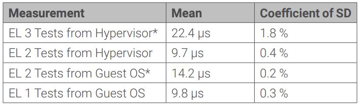
The measurements marked with (*) include the round-trip Exception level transitions (SMC from hypervisor and hypercall from guest OS) in the measurements.
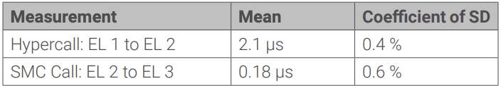
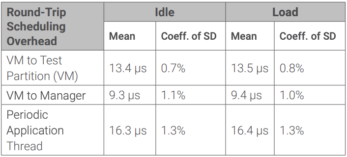
The Exception level switch overhead alone between guest OS, hypervisor, and TF-A is dependent on the implementation of the handlers, and it can be an indicator for the choice of where to implement the STL calls in a system. The following table gives the measurements for executing round-trip hypercalls into the hypervisor and SMC calls into the TF-A over 10,000 iterations on each core.
Depending on the implementation in a dedicated test partition with a guest OS, the manager thread in the hypervisor, or the applicationlevel thread, the scheduling of the STL has a different overhead due to the context switch from the application. The transitions were measured as round-trip times, where the scheduled entity collected only the timing data, and for the rest of the time the system either called the PMU or generic timer in a close loop (idle scenario) or performed permanent memory writing to an array of 20MB to simulate high bus and cache load (load scenario). The data has been collected over at least 400 iterations each.
Integration Example 1: Dedicated Test Partition
The total overhead of running the STL on all cores of the quad-core Xilinx Zynq UltraScale+ MPSoC with Helix Platform is measured to assess a real-world scenario and determine a rough order of magnitude of computing time that the STL requires in a system. The STL can be scheduled independently for each processor core, so the overhead for cross-core synchronization of the tasks can be avoided.
The demonstrator for the dedicated test partition implements the STL execution at EL 2 and EL 3 for maximum coverage in tasks with core affinity, where the OS functionality for periodic activation of tasks is used. Timestamps are taken from the guest OS level before and after the STL execution is initiated through a hypercall API.
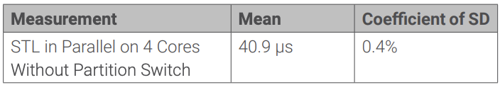
The result is slightly higher than the sum of the numbers for the hypercall from EL 1 to EL 2 plus the execution of the STL on EL 2 and EL 3, but it is still in the expected range.
The complete time of the dedicated test partition will include the time to switch the application VM out and in again, which is around 13.5 µs per STL run. Therefore, the net execution per STL cycle is about 55 µs including the partition switch, although the static time window length for the test partition must be configured to include worst-case scenarios.
Assuming a system with a realistic FTTI of 10ms, the execution of the STL on all four cores requires about 0.5% of the overall available computing time in this demonstrator system without worstcase overhead.
Integration Example 2: Hypervisor Manager
While the dedicated test partition requires switching from one VM context at EL 1 to a different one — including, for example, different memory mappings that require replacement of TLB entries in the MMU — the implementation of the STL in a hypervisor manager also removes the costly round trip of transition between the guest OS (EL 1) and the hypervisor (EL 2), as it runs within the same hypervisor context as the system-level scheduling.
This reduces the time for context switch and execution of the STL from about 55 µs for the test partition with guest OS down to 50 µs. As with the dedicated test partition, the static time window must be configured to accommodate worst-case scenarios.
For our example system with an FTTI of 10ms, the net overhead of the Arm STL is again in the range of 0.5% for this approach.
Integration Example 3: Execution in Application Context
Implementing the STL execution in a high-priority periodic task within the application partition and independently on each core, the impact on the available computing can be reduced as the processor is released immediately after completing the STL and priority-preemptive tasks can reclaim processor time. This allows measuring the actual time that normal processes are interrupted during STL execution. Scheduling the STL from the application level reintroduces the overhead of the hypercall API and, depending on the design of the guest OS, an additional transition from user space (EL 0) to the guest OS kernel (EL 1) could be required.
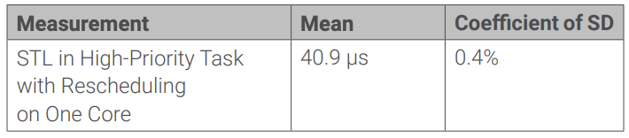
When executing the STL independently on each core, without the need for cross-core synchronization of the tasks, the results demonstrate the small impact of periodic execution of the STL in a task in a safety-critical VxWorks guest OS.
Again, under the assumption of an FTTI of 10ms, the available computing time is reduced by 0.6%. This number is slightly higher than for the approaches with a separate VM or manager; however, there is no need to statically allocate time for worst-case scenarios, as in the other cases.
CONCLUSION
The integration of the Arm STL in a demonstrator system with Helix Platform shows that the impact on overall system performance is in the order of 0.5% on an actual Cortex-A53 system with assumed FTTI of 10ms. Different practical approaches to integrate the STL within a complex safety-certifiable OS architecture are discussed and demonstrated; each solution offers slightly different advantages, while the OS overhead is within the same range. This gives the designer or system integrator of a safety system a set of options to ensure the best alignment with the technical, safety, and project organization requirements, especially for complex scenarios in which independent applications of different safety-criticality or from different vendors need to be integrated into one system.
The Helix Platform OS offers proven functionality with a safety-certification pedigree to schedule the STL and monitor timely execution and jitter, and a health monitoring framework records failures and takes appropriate actions in case the test execution detects a hardware failure.
The highest-level coverage of the Arm STL can only be achieved by including the tests that run on Exception level 3 of the processor, which is out of the scope of an OS and is managed by the TF-A on commercial processors. Integrating the Arm STL with the TF-A on the Xilinx processor is only a small technical challenge, due to the few assumptions on the execution environment for the test library. In certain cases, the additional coverage of EL 3 tests may not be required to achieve the desired safety goals, thus simplifying development. Actual projects might see challenges in different responsibilities for integration of the STL libraries with the OS or applications and the platform firmware, and system designers should take this into account early in the process.
The demonstration in this white paper focuses only on the software–software integration aspects of the Arm STL and does not go into the hardware-specific aspects of the integration of the Cortex-A53 processor core into the Xilinx Zynq MPSoC design, except that some tests had to be deactivated as they do not apply to this specific processor design.
For more details on the integration and code examples, please contact your Wind River representative for access to a Technical Note.
REFERENCES
- N. Menon, “The Flexible Approach to Adding Functional Safety to a CPU,” October 2020, www.arm.com/products/development-tools/ embedded-and-software/software-test-libraries
- ARINC Inc., “Avionics Application Software Standard Interface, Part 0, Overview of ARINC 653, Supplement 2,” SAE-ITC, 2019
- RTCA/EUROCAE, “DO-297/ED-124 Integrated Modular Avionics Development Guidance and Certification Considerations,” 2005
- Arm Limited, “SMC Calling Convention, ARM DEN 0028E 1.4,” 2022
- Arm Limited, “ARM Cortex-A53 MPCore Processor TRM r0p4,” 2014